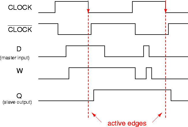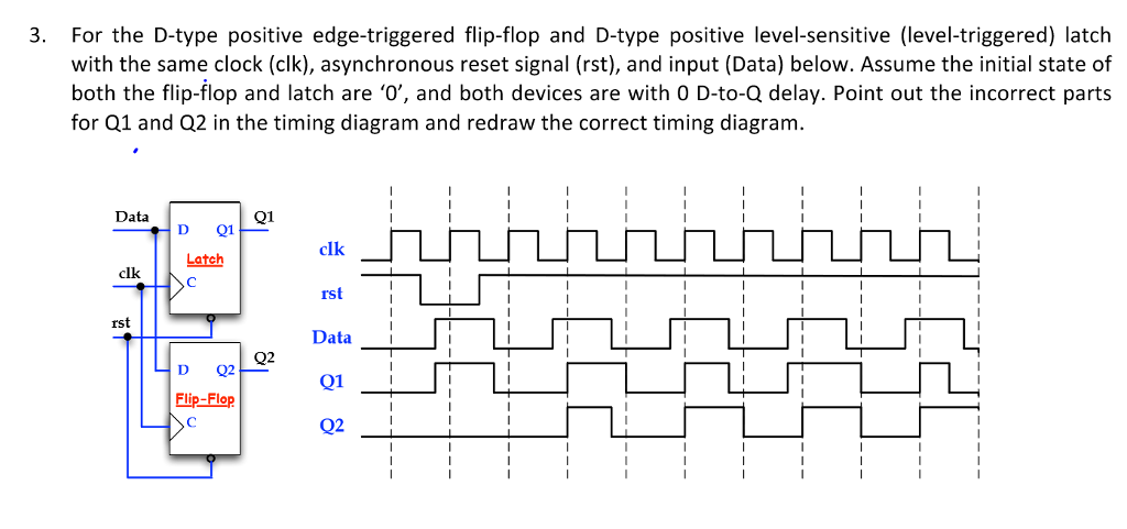

The output of the T flip-flop “toggles” with each clock pulse. As shown in figure, the T flip-flop is obtained from the JK type if both inputs are tied together. The T flip-flop is a single input version of the JK flip-flop.

The first flip flop (master flip flop) is connected with a negative clock signal i.e inverted and the second flip flop (slave flip flop) is connected with double inverse of clock signal i.e.

Inputs J and K behave like inputs S and R to set and clear the flip-flop (note that in a JK flip-flop, the letter J is for set and the letter K is for clear). The Master slave D flip flop shown below is a positive edge triggered device that means it will operate when clock input has raising edge. If it is 0, the flip-flop switches to the clear state.Ī JK flip-flop is a refinement of the SR flip-flop in that the indeterminate state of the SR type is defined in the JK type. If it is 1, the flip-flop is switched to the set state (unless it was already set). The D input is sampled during the occurrence of a clock pulse. The D input goes directly into the S input and the complement of the D input goes to the R input. The D flip-flop shown in figure is a modification of the clocked SR flip-flop. SR Flipflop truth table VHDL Code for SR FlipFlop library ieee This type of flip-flop is referred to as an SR flip-flop. Each flip-flop has two outputs, Q and Q’, and two inputs, set and reset. A flip-flop circuit can be constructed from two NAND gates or two NOR gates.


 0 kommentar(er)
